
Corrugated Packaging Cutting & Creasing Solutions | DXOVO
DXOVO digital cutting and creasing solutions help packaging teams develop corrugated samples, revise designs and handle short runs without dedicated cutting dies.
Table of Contents
Corrugated Packaging Cutting Solutions: From Design Changes to Short-Run Production
A revised box design should not bring the packaging workflow to a standstill. Yet for many corrugated converters, packaging developers and in-house production teams, a small change can trigger another round of manual cutting, outsourced sampling or prototype tooling.
The difficulty is especially visible in custom packaging, product launches and short production runs. Customers want a physical sample quickly, but the order may be too small—or the design too uncertain—to justify a dedicated cutting die.
DXOVO manufactures CNC oscillating knife cutting machines in China. For suitable corrugated applications, digital knife cutting and creasing provide a practical route from a structural drawing to a folded sample or short-run packaging blank. The configuration depends on the board, finished part and production requirements.
Where Traditional Packaging Preparation Creates Bottlenecks
Manual Sampling Uses Valuable Production Time
Hand-cutting a corrugated sample involves more than following an outline. An operator must transfer dimensions, cut slots and tabs, prepare fold lines, assemble the structure and correct fit problems.
Results can depend heavily on individual experience. When several revisions are needed, skilled staff spend more time repeating preparation work instead of developing new packaging structures or supporting production.
Design Changes Increase Tooling Costs
A dedicated cutting die can be appropriate once the structure is approved. Before that point, changes to a locking tab, internal divider or box dimension may require additional tooling work.
The cost extends beyond the die itself. Purchasing, delivery, testing and further adjustments can lengthen the approval cycle.
Small Orders Interrupt the Main Production Schedule
A production line organised around repeat orders may struggle to accommodate frequent, low-quantity jobs. Setup and scheduling can consume a disproportionate share of the order’s value.
Outsourcing introduces another dependency. The converter must coordinate an external supplier while still meeting the customer’s deadline.
How Digital Knife Cutting Improves the Workflow
A digital cutting system follows prepared cutting and creasing paths to process the packaging blank. When the design changes, the operator updates the file and prepares another sample without ordering a dedicated cutting die for that iteration.
This creates a separate workflow for structural development and selected short runs.
| Existing production difficulty | Improvement available through a suitable digital workflow |
|---|---|
| Repeated manual tracing and trimming | Cutting paths come from the prepared digital design. |
| Prototype tooling required during design development | Design iterations can be evaluated without a dedicated cutting die. |
| Sampling depends on an external production queue | Suitable samples can be prepared in-house when staff and capacity are available. |
| Short jobs disrupt an established production schedule | Selected short runs can move to a separate digital cutting cell. |
| Repeat samples depend on operator memory | Approved files and documented settings provide a controlled starting point. |
Material loading, file preparation, inspection and assembly remain part of the production process. Including these steps in the workflow makes the improvement easier to measure.
Match the Cutting Process to the Corrugated Board
Board Construction Determines the Cutting Requirements
“Corrugated cardboard” is not a complete material specification. Flute construction, liner quality, thickness, coatings and board condition can affect cutting and folding behaviour.
An application review should establish:
Board grade, flute designation and measured thickness.
Single-wall or double-wall construction.
Sheet dimensions, flatness and flute direction.
Printed surfaces, coatings, laminations and adhesive layers.
Required slots, tabs, openings and finished box dimensions.
Supported board construction and thickness should be confirmed against the proposed DXOVO configuration using a representative material sample.
Cutting and Creasing Must Work Together
A clean outline does not automatically produce a satisfactory box. The blank must fold, lock and assemble correctly.
Knife and blade selection should suit the board and part geometry. Creasing wheel selection and settings should account for the board construction, fold direction and intended structure.
For printed packaging, alignment between the artwork, cutting outline and crease positions also matters. Camera-assisted registration can be included where the application requires it.
Evaluate the Finished Package
Inspect the Features That Affect Assembly
A sample review should examine liner tearing, incomplete cuts, excessive edge compression, damaged corners and cracking along folds.
Confirm that locking tabs engage, slots align and internal components fit together. Where possible, evaluate the assembled package around the intended product.
For protective packaging, structural fit and cutting quality should be assessed alongside the relevant packaging performance requirements.
Review Relevant Video and Sample Evidence
Demonstration footage should show material positioning, cutting, creasing, part removal and the assembled result.
Identify the board, tooling and whether the footage has been accelerated. Cutting time should be distinguished from the complete loading-to-unloading cycle.
Close-up photographs help evaluate cut edges, fold lines, internal openings and assembled corners. Dimensional results should identify the feature measured and the measurement method.
Select Equipment Around the Packaging Task
The configuration should follow the job rather than the longest available options list.
| Configuration area | Selection criteria |
|---|---|
| Knife cutting | A suitable oscillating knife or alternative knife tool and blade for the board. |
| Creasing | Tooling matched to the board construction and fold requirements. |
| Working area | Sufficient usable space for the sheet size and nesting layout. |
| Material holding | An arrangement that keeps the board stable during processing. |
| Registration | Camera-assisted alignment when printed work requires it. |
| Handling | Loading and unloading arrangements suited to batch size and staffing. |
A DXOVO configuration proposal should connect these choices to the intended packaging application and clearly distinguish included equipment from optional tooling.
Connect Structural Design to Production
From Drawing to Approved Sample
A repeatable workflow starts with the drawing and ends with an inspected package:
Confirm the packaging structure, dimensions and flute direction.
Assign cutting, creasing and marking operations in the design.
Arrange the parts on the sheet and review material use.
Prepare the tooling and load the board.
Cut and crease the blank.
Assemble, inspect and revise the design where necessary.
Retain the approved file and production settings.
Confirm the Software and File Workflow
Use a representative file from the software your designers already work with. Confirm units, supported formats, layer interpretation and any nesting or registration requirements in the selected software configuration.
A documented workflow creates a clearer handoff between packaging design and production and makes repeat jobs less dependent on individual operator experience.
Calculate the Return on Investment
The investment case should use production records: outsourced sampling invoices, prototype die charges, paid overtime, material rework and the time spent on representative jobs.
Example Based on a $20,000 Initial Investment
The following example assumes a total installed investment of $20,000. All figures are in US dollars.
| Monthly change | Cash benefit or additional cost |
|---|---|
| Avoided outsourced sampling and short-run service charges, excluding dies | +$1,800 |
| Avoided prototype cutting-die purchases | +$900 |
| Reduced paid overtime | +$1,500 |
| Reduced material scrap and rework, excluding labour already counted | +$600 |
| Additional consumables, electricity and maintenance provision | −$800 |
| Net monthly cash benefit | $4,000 |
Simple payback = initial investment ÷ net monthly cash benefit
$20,000 ÷ $4,000 = 5 months
12-month simple ROI = [(12 × net monthly cash benefit) − initial investment] ÷ initial investment × 100
[($4,000 × 12) − $20,000] ÷ $20,000 × 100 = 140%
At this level of savings, the annual net operating cash benefit is $48,000, leaving $28,000 after recovering the initial investment.
These calculations assume the full monthly benefit is achieved throughout the year, before financing and taxes. Actual results depend on utilisation, operating costs and the savings achieved.
How Utilisation Changes the Return
| Net monthly cash benefit | Simple payback | 12-month simple ROI |
|---|---|---|
| $2,000 | 10 months | 20% |
| $4,000 | 5 months | 140% |
| $6,000 | Approximately 3.3 months | 260% |
Suitable job volume is central to the business case. A machine processing regular samples and short-run orders has a different financial profile from one used occasionally.
Separate Labour Capacity from Cash Savings
For example, reducing operator involvement from 20 minutes to 8 minutes across 1,000 comparable work cycles would release 200 hours per month.
At a loaded labour cost of $30 per hour, those hours represent $6,000 of available labour capacity. They do not automatically reduce payroll by the same amount.
If employees move to other work, the benefit is additional capacity. In the cash example above, only the $1,500 reduction in paid overtime is counted as labour-related savings. Adding the full $6,000 again would overstate the return.
Additional orders should contribute their achievable margin after additional costs—not their gross sales value—to the investment calculation.
Improve the Product Line Without Moving Every Job
For a converter handling structural samples, frequently revised mailers and small product-launch orders, a digital cutting cell can take responsibility for design iterations and selected short runs.
Once a structure is approved, subsequent orders can remain digital or move to conventional tooling according to quantity, complexity and production cost.
This division can reduce low-quantity interruptions on the main production line while giving the design team more direct control over sample preparation.
It can also support a broader product offer:
Custom-sized corrugated boxes.
Product-specific inserts and dividers.
Trial packaging for new products.
Small launch batches.
Repeat short orders with changing dimensions.
Each application must remain technically suitable and commercially viable. For an established, unchanged design in a long repeat run, conventional die cutting may remain the more economical route.
Plan Installation and Ongoing Support
The quotation should identify the working area, tool heads, software and any handling or registration options included.
Site preparation should address machine access, operator space, sheet storage, electrical supply and configuration-specific utility requirements.
Before purchase, confirm installation arrangements, operator training, maintenance guidance, consumable blades, spare parts and remote technical support. Service availability and warranty terms should be documented in the agreed commercial conditions.
Request a Corrugated Packaging Application Review
Send DXOVO the board grade, flute type, thickness, sheet size and a representative structural drawing. Include the finished dimensions, critical features, printed registration requirements and expected edge quality.
For an ROI evaluation, provide typical batch sizes, target output and the sampling, tooling, overtime or rework costs you want to address.
Request a material test and configuration proposal from DXOVO. Use your own board, drawings and cost records to establish where digital cutting can improve the packaging workflow and whether the investment is justified.
A cutting solution starts with the finished part: its material, geometry and role in your production process. Share a drawing or representative part so the proposed setup can be assessed against your requirements.
Which configuration fits the part?
The proposed configuration should identify the working area, knife or other processing tools, material holding and feeding method. Blade choice depends on material behaviour and the features to be cut.
Distinguish included equipment from optional tooling before comparing quotations.
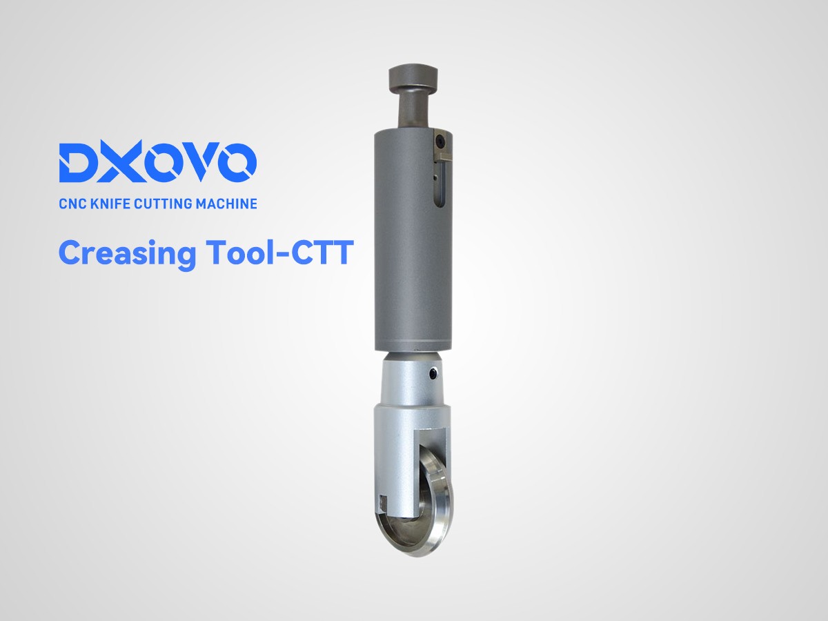
Tooling for this application.
test11111111111111111111111111
11111111111111111111111111112222222222222222223333333333333333333333333333333333333333334444444444444444444444444444444444444444444444444445…
View cutting tool ↗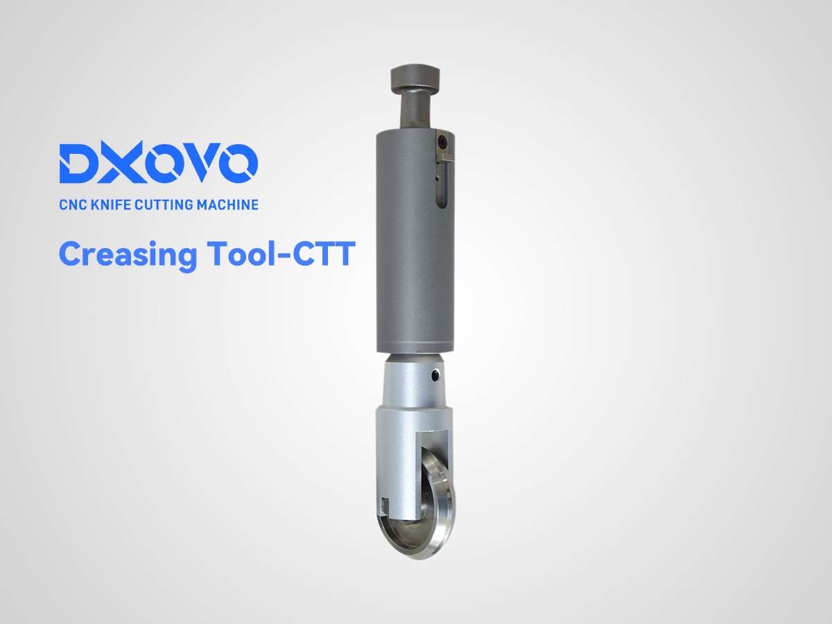
22222222222222222222222
11111111111111122222222222222222233333333333334444444444444444455555555555555555555555566666666666666666666667777777777777777777777888888888…
View cutting tool ↗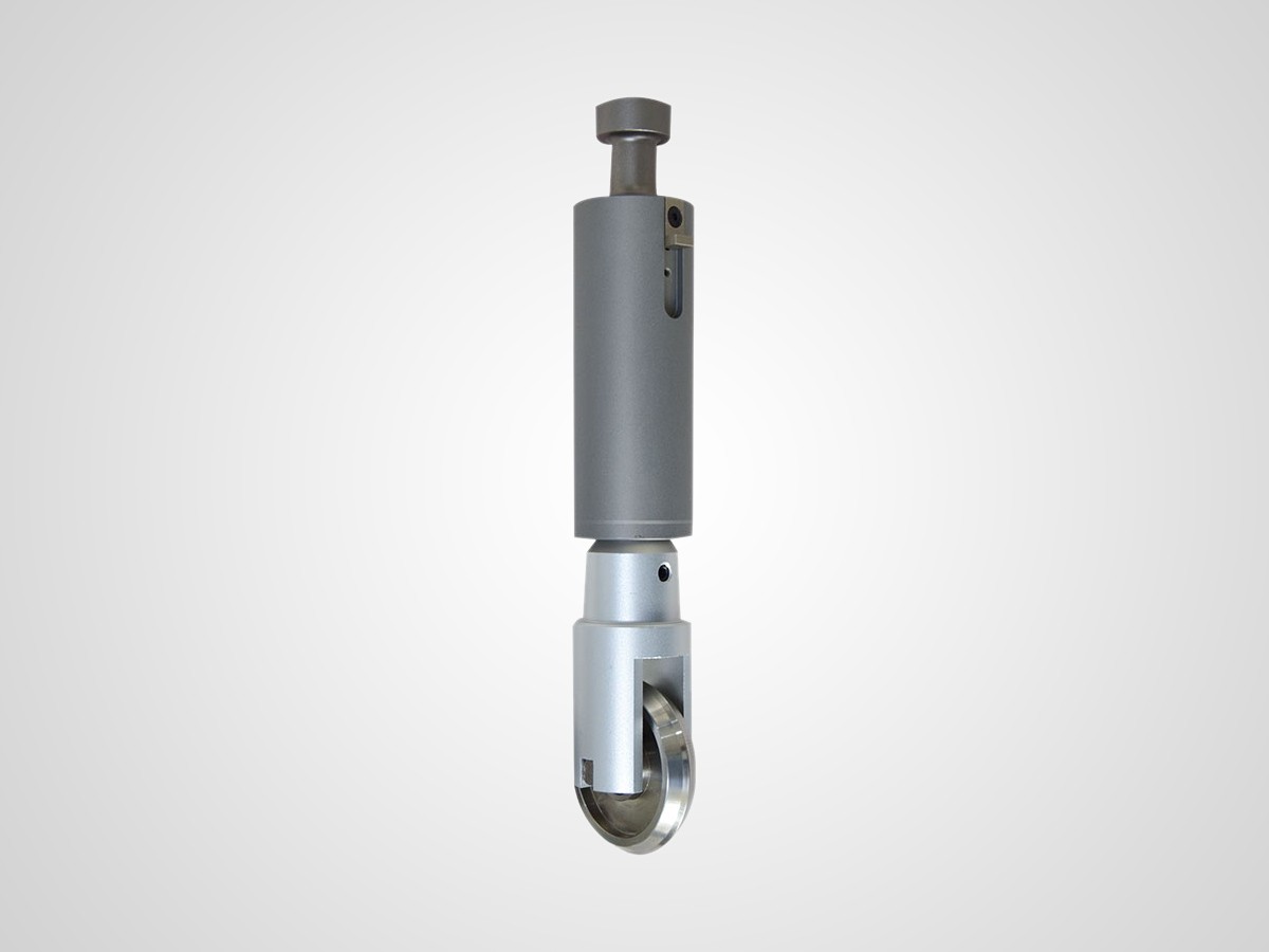
tool test
testssssssssssssssssssssssssssssssssssssssssssssssssssssssssssssssssssssssssssssssssssssssssssssssssssssssssssssssssssssssssssssssssssssssss…
View cutting tool ↗test11111111111111111111111111
11111111111111111111111111112222222222222222223333333333333333333333333333333333333333334444444444444444444444444444444444444444444444444445…
View cutting tool ↗test11111111111111111111111111
11111111111111111111111111112222222222222222223333333333333333333333333333333333333333334444444444444444444444444444444444444444444444444445…
View cutting tool ↗test11111111111111111111111111
11111111111111111111111111112222222222222222223333333333333333333333333333333333333333334444444444444444444444444444444444444444444444444445…
View cutting tool ↗A cutting system for this application.
Review the proposed machine, then confirm tooling and material handling against your production requirements.

product one
Chemical equipment (the English name is Chemical Equipment) is a part of chemical machinery. Chemical machinery consists of two parts. The first part is chemical machinery, mainly …
View machine details ↗Why this configuration fits.
See the process on the material.
Ask for cutting footage relevant to your material and part. Review material positioning, the cutting sequence and the finished result together with the test conditions.
Request application footage ↗Review the material, tool setup and finished part shown in the demonstration.
Inspect the cutting results.
Review the edges, openings and features that matter to your part. Share the required finish and acceptance criteria to discuss a representative sample evaluation.
Discuss your sample requirements ↗What needs to be confirmed by testing?
Coatings, backing layers, reinforcement, material movement and very small features can change the cutting requirements. Materials with the same commercial name may behave differently.
Discuss the acceptable edge, tolerances and any restrictions before assuming a result will transfer to your material.
Compare documented customer projects.
Review the customer's material, production context and recorded results before drawing comparisons with your application.
testttttttttttttttt
6666666666666666777777777777777777777777777777777777777777777777777777777777777777777777777777777777777777777777777777777777777777777777777777777777777777777777777777777777777777777777777777777777777777777777777777777777…
Read the customer case ↗
00000000000000000000000000000000000000000000
7777777777777766666666666666666666666666666666666999999999999999999999999999999999999999999999999999999999999999999999999999999999999999999999999999999999999999999999999999999999999999999999999999999999999999999999999999…
Read the customer case ↗
666666666666666666666666666666666666666666666666666666666666666666666666666
4444444444444444444444444444444444444444444444444444444444444444444444444444444444444444444444444444444444448888888888888888888888888888888888888888888888888888888888222222222222221111111111111111111111111111111111111111…
Read the customer case ↗Review the machine configuration.
Tooling, working area and material handling should be confirmed against the requirements of your application.
product one
Chemical equipment (the English name is Chemical Equipment) is a part of chemical machinery. Chemical machinery consists of two parts. The f…
View machine details ↗
Product Two
Chemical equipment (the English name is Chemical Equipment) is a part of chemical machinery. Chemical machinery consists of two parts. The f…
View machine details ↗
Product Three
Chemical equipment (the English name is Chemical Equipment) is a part of chemical machinery. Chemical machinery consists of two parts. The f…
View machine details ↗